IPSec VPN between a Palo Alto Networks Firewall and a Cisco Router
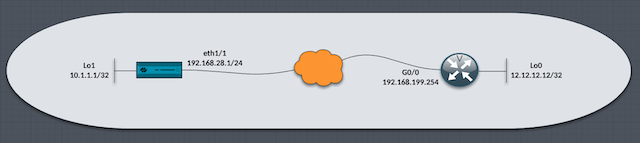
In my EVE-NG lab, I've configured static IPSec Site-to-Site VPN between a Palo Alto Networks VM-Series firewall running PAN-OS 9.1.12 and a Cisco IOSv router running the VIOS-ADVENTERPRISEK9-M 15.9 image.
The PAN firewall has connectivity through the lab internet backbone to the Cisco router. Both the firewall and the router have a /32 loopback IP address configured so that I can do a simple ping test between the networks when the IPSec Site-to-Site VPN is established.
These are configuration steps I took to get the VPN up and running, excluding the initial loopback address, interface configurations and Zone configuration.
Firewall Configuration
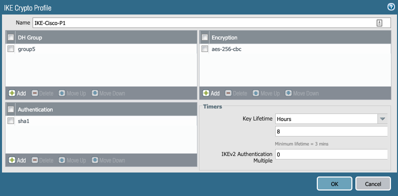
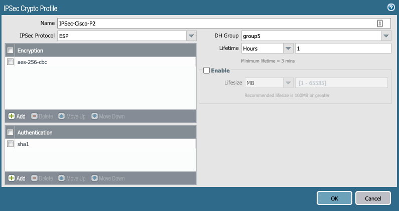
- IKE (Phase1) and IPsec Crypto(Phase2) Profiles. I chose aes256, sha1, PFS group 5 and a lifetime of 8hrs.
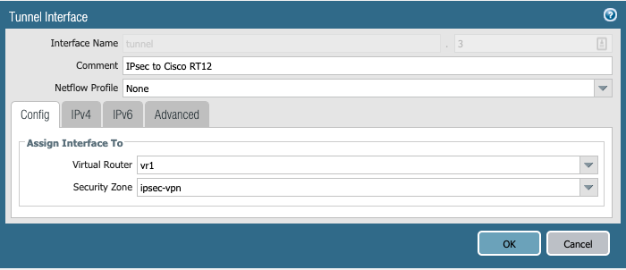
2. Tunnel interface. I assigned it to the vr1 virtual router and the IPSec-VPN security zone. There is no need for me to configure an IP address as I'm not using dynamic routing protocols in this lab.
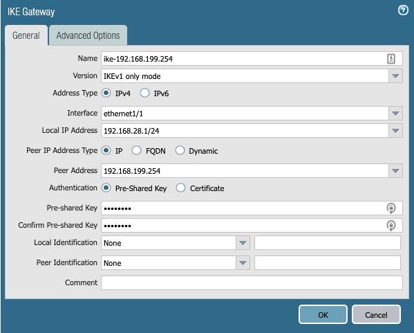
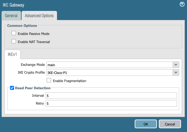
3. IKE Gateway configuration, I configured the egress interface of the firewall, including the local IP address, the remote peer IP address and I chose to use a pre-shared key (password) as the authentication method. The password here needs to be the same on the remote peer device. In the advanced options tab and under the IKEv1 section, I selected main as the exchange mode and chose the IKE Crypto Profile (Phase1) I defined earlier.
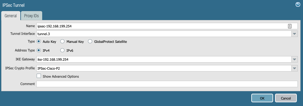
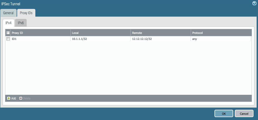
4.IPSec tunnel. Now it's time to bring all this configuration together in the IPSec section of the firewall, I selected the tunnel.3 interface, the IKE gateway (remote peer) and the IPSec Crypto profile (Phase2). I'm aware that Palo Alto Networks Firewalls only support route-based VPNs and the fact I will be configuring a Policy-Based VPN on the remote Cisco router, I will need to use Proxy ids. Devices that support policy-based VPN use specific security rules and policies or access lists (source addresses, destination addresses and ports) for permitting interesting traffic through an IPSec tunnel. These rules are referenced during quick mode/IKE phase 2 negotiation and are exchanged as proxy IDs in the first or the second message of the process. So that being said, I went ahead and configured a Proxy ID specifying the local and remote networks, which in my case is the two /32 IP addresses.
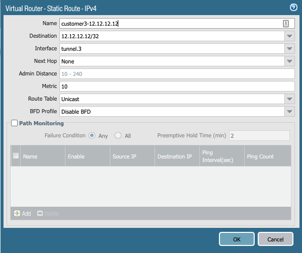
5 . Static route needs to be configured in the virtual router to route the correct traffic through the corresponding tunnel. The destination is 12.12.12.12/32 which needs to be sent to tunnel3 with the next hop of none.
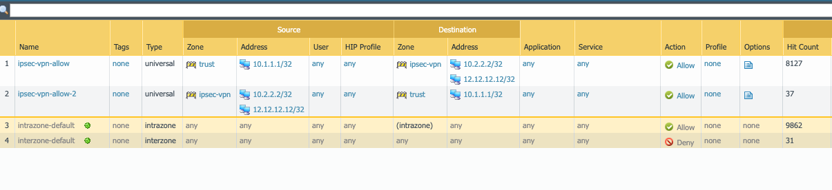
6. Security Policies then need to be configured to allow traffic in both directions. I have two VPN tunnels configured on the firewall, that's why I have an additional address object. For this lab, traffic should allow bi-directional traffic between 10.1.1.1/32 and 12.12.12.12/32.
Cisco Router Configuration
1.The ISAKMP (Phase1) Policy and the authentication key needs to be configured to peer with the remote Palo Alto Firewall. Below is for policy 1 which uses AES 256 for encryption, the authentication method is pre-shared key (password) Diffie-Hellman Group 5 and an IKE lifetime of 28800 secs which is 8hrs. I used the simple password Pal0Alto as the preshared key password and specified the remote peer's IP address.
crypto isakmp policy 1
encr aes 256
authentication pre-share
group 5
lifetime 28800
crypto isakmp key Pal0Alt0 address 192.168.28.1
2. An Access-List is used to identify interesting traffic, in my case I wanted to identify traffic sourcing from 12.12.12.12/32 destined to 10.1.1.1/32 networks.
access-list 100 permit ip host 12.12.12.12 host 10.1.1.1
3. The IPSec (Phase2) policy needs to be defined by specifying exactly which hashing and encryption methods to use. In Cisco land, this policy is called a "transform-set"
crypto ipsec transform-set MYTRANSET esp-aes 256 esp-sha-hmac
4. A Crypto Map is used to bind all the configurations together. This is how the Crypto Map is processed. If traffic matched is by access-list 100, then set my peer to be 192.168.28.1 (firewall) and use the transform-set MYTRANSET , use Perfect Forward Secrecy using Diffie-Hellman Group 5 (make sure both sides support this)
crypto map MYMAP 1 ipsec-isakmp
set peer 192.168.28.1
set transform-set MYTRANSET
set pfs group5
match address 100
5. Apply the Crypto Map "MYMAP" to the egress interface, this turns on the policy and kicks starts the IPSec Tunnel setup.
interface Loopback0
ip address 12.12.12.12 255.255.255.255
!
interface GigabitEthernet0/0
ip address 192.168.199.254 255.255.255.0
duplex auto
speed auto
media-type rj45
crypto map MYMAP
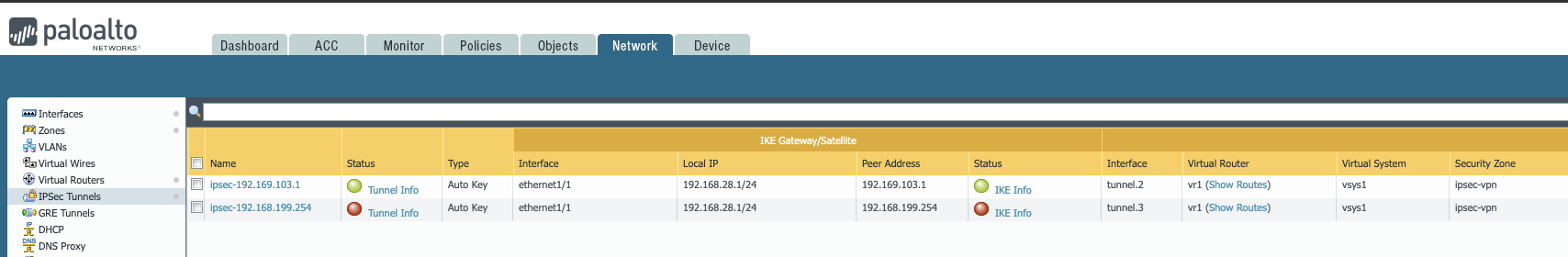
6. Now we can verify if the Tunnel has come up. On the Palo Alto Network Firewall under the Network tab and the IPSec Tunnels section, in the Status Column traffic lights, colours are used. If the statuses are green then everything is looking good. If they are red, some further troubleshooting is required.
NOTE: There is no requirement to add a static route, unlike the Palo Alto Firewall, as this is a policy-based VPN that makes routing decisions based on the access list.
Initially, the IPSec Tunnel to the Cisco router is showing down.
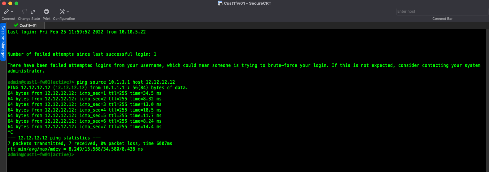
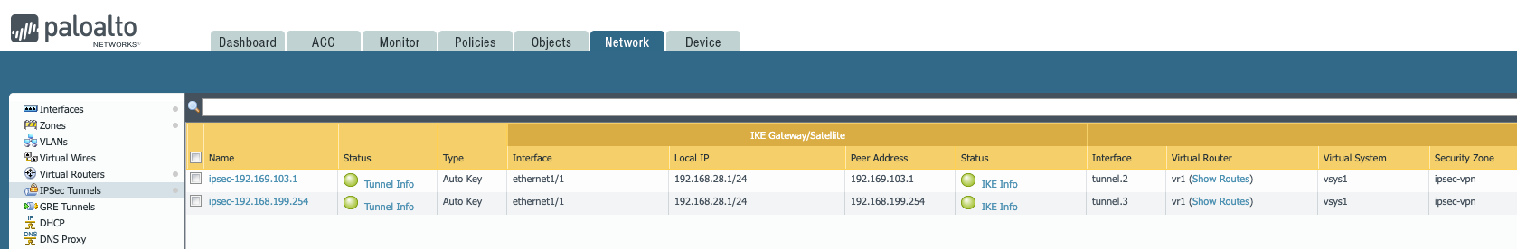
I performed a source ping - ping source 10.1.1.1 host 12.12.12.12 and I got a response, I can now see that the status has turned green in the Firewall WebUI.
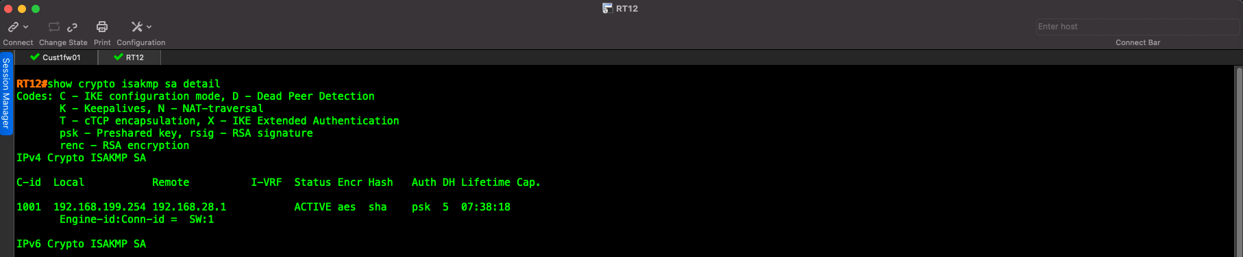
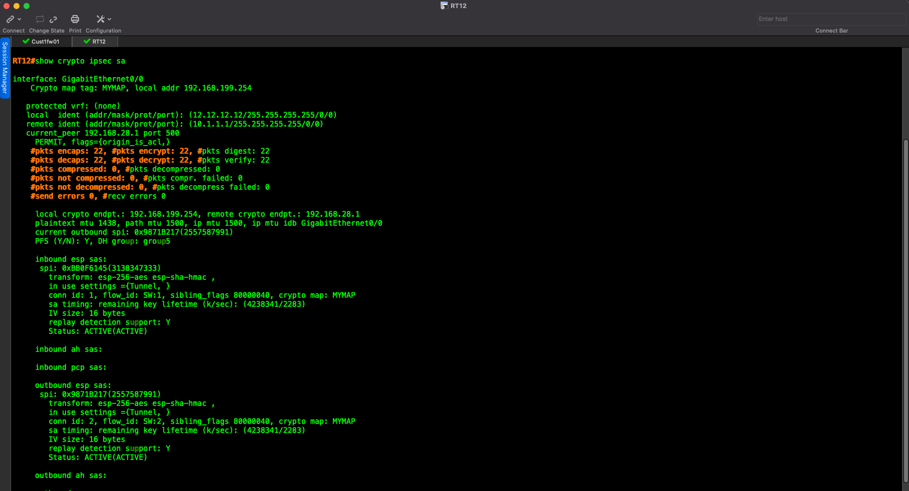
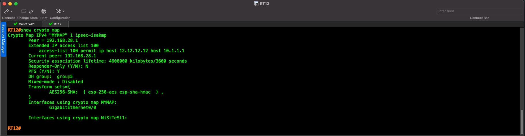
The Cisco router can show details on IPSec VPN Tunnel using these commands:
- show crypto isakmp sa detail
- show crypto ipsec sa
- show crypto map